Tutorial : How to build cellphone operated Robot

Here in this tutorial I will show you how you can control things from anywhere with the help of your cellphone.
Here I show you this by controlling my robot with the help of my phone.You can use this technique for any kind of wireless communication where you won’t required much more signals.
I build this circuit to control my robot wirelesly,basically Wireless-controlled robots use rf circuits, which have the drawbacks of limited working range, limited frequency range and the limited control. Use of a mobile phone for robotic control can overcome these limitations. It provides the advantage of robust control, working range as large as the coverage area of the service provider, no interference with other controllers and up to twelve controlles.
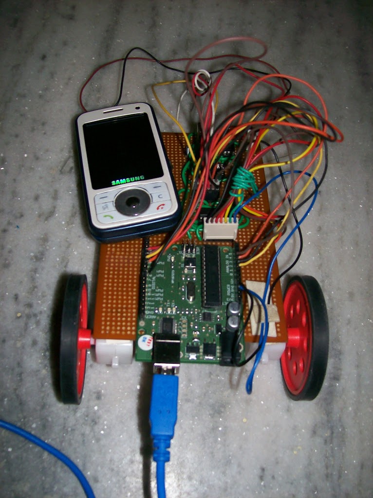
Step 1 : Overview ->
robot, is controlled by a mobile phone that makes call to the mobile phone attached to the robot in the course of the call, if any button is pressed control corresponding to the button pressed is heard at the other end of the call. This tone is called dual tone multi frequency tome (DTMF) robot receives this DTMF tone with the help of phone stacked in the robot,
The received tone is processed by the Arduino with the help of DTMF decoder MT8870 the decoder decodes the DTMF tone in to its equivalent binary digit and this binary number is send to the Arduino, the Arduino is preprogrammed to take a decision for any give input and outputs its decision to motor drivers in order to drive the motors for forward or backward motion or a turn.
The mobile that makes a call to the mobile phone stacked in the robot acts as a remote. So you do not require the construction of receiver and transmitter units.
DTMF signaling is used for telephone signaling over the line in the voice frequency band to the call switching center. The version of DTMF used for telephone dialing is
known as touch tone.
DTMF assigns a specific frequency to each keys that it can easily be identified by the electronic circuit. The signal generated by the DTMF encoder is the direct al-gebric submission, in real time of the amplitudes of two sine waves of different frequencies, i.e. ,pressing 5 will send a tone made by adding 1336hz and 770hz to the other end of the mobile. The tones and assignments in a dtmf system shown below :

Step 2 : Circuit ->
Components: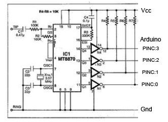 the notations are :
ic1 – mt8870
ic4 – cd7004
r1,r2 – 100k resistances
r3 – 330k resistances
r4-r7 – 10k resistances
c1- 0.47 micro farat capacitor
c2,c3 – 22pfarat capacitor
c4 – 0.1micro farat capacitor
xtal1 – 3.57 mhz crytal
batt- 6v
Note : two cellphones are require.
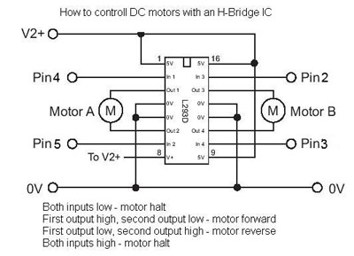
An MT8870 series dtmf decoder is used here. All types of the mt8870 series use digital counting techniques to detect and decode all the sixteen DTMF tone pairs in to a four bit code output. The built -in dila tone regection circuit eliminated the need for pre- filtering.I connect this output 4bit signal with PortC of Arduino Board. Arduino is programmed to read this signals and generate output accordingly on its Digital Pins which are connected with L293d Motor Driver.
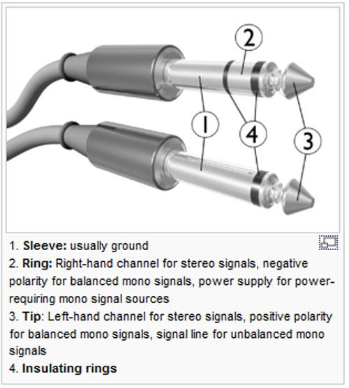
these connections are
1. Tip
2. Ring
i’ll prefer to use handsfree which have a straight jack (similar to the ones which we use in our ipods, but a thinner one)
- the tip of that jack is called the “tip”
- the rest part behind the tip after a black strip is the ring So connect these two connections with the circuit and you will be done
Step 4: Working
In order to control the robot, you have to make a call to the cellphone attached to the robot from any phone.
now the phone is picked by the phone on the robot through auto answer mode(which is in all the phone, just enable it).
now,
when you press 2 the robot will move forward
when you press 4 the robot will move left
when you press 8 the robot will move backwards
when you press 6 the robot will move right
when you press 5 the robot will stop.
Step 5 : Code ->
int motor1Pin2 = 5;
int motor2Pin1 = 2;
int motor2Pin2 = 3;
int motorsPinEnable = 7;
int i=0,k=0,m=0;
void setup()
{
pinMode(motor1Pin1, OUTPUT);
pinMode(motor1Pin2, OUTPUT);
pinMode(motor2Pin1, OUTPUT);
pinMode(motor2Pin2, OUTPUT);
pinMode(motorsPinEnable, OUTPUT);
digitalWrite(motorsPinEnable,HIGH);
DDRC = 0x00;
DDRD = 0xFF;
}
void loop()
{
i = PINC;
k = i & 0xFF;
if(m != k)
{
switch (k)
{
case 0x02:
{
forward();
m=k;
break;
}
case 0x18:
{
backward();
m=k;
break;
}
case 0x04:
{
left();
m=k;
break;
}
case 0x06:
{
right();
m=k;
break;
}
default:
{
m=0;
break;
}
}
}
}
void forward()
{
digitalWrite(motorsPinEnable,HIGH);
digitalWrite(motor1Pin1, LOW);
digitalWrite(motor1Pin2, HIGH);
digitalWrite(motor2Pin1, HIGH);
digitalWrite(motor2Pin2, LOW);
delay(1000);
digitalWrite(motorsPinEnable,LOW);
}
void backward()
{
digitalWrite(motorsPinEnable,HIGH);
digitalWrite(motor1Pin1, HIGH);
digitalWrite(motor1Pin2, LOW);
digitalWrite(motor2Pin1, LOW);
digitalWrite(motor2Pin2, HIGH);
delay(1000);
digitalWrite(motorsPinEnable,LOW);
}
void left()
{
digitalWrite(motorsPinEnable,HIGH);
digitalWrite(motor1Pin1, LOW);
digitalWrite(motor1Pin2, HIGH);
digitalWrite(motor2Pin1, LOW);
digitalWrite(motor2Pin2, HIGH);
delay(1000);
digitalWrite(motorsPinEnable,LOW);
}
void right()
{
digitalWrite(motorsPinEnable,HIGH);
digitalWrite(motor1Pin1, HIGH);
digitalWrite(motor1Pin2, LOW);
digitalWrite(motor2Pin1, HIGH);
digitalWrite(motor2Pin2, LOW);
delay(1000);
digitalWrite(motorsPinEnable,LOW);
}
Unknown
May 7, 2013 at 5:54 pmcan u mail me a complete circuit diagram with audrino?
praga_deesan@yahoo.co.in