In this tutorial I will show you how to build a quite fancy 8 by 10 L.E.D matrix(with scrolling text and animations) using the Arduino and 4017 decade counter. This type of matrix is easy to make and program and it is a good way learn about multiplexing.
Components :
1. 80 L.E.D.s
2. 8 resistors( The value is determent by the type of L.E.D.s)
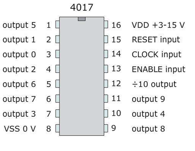
3. 4017 decade counter
4. 10 1KOhm resistors
5. 10 2N3904 transistors
6. Some single core wire
7. GCB
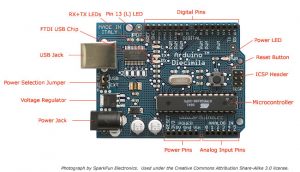
8. Arduino
Step 1 : How to choose LEDs
This is one of the most important part of this project, because it based on LEDs it’s very critical to choose the right ones.I recommend using 5mm diffused LEDs because they give a good amount of light and make a clear image.
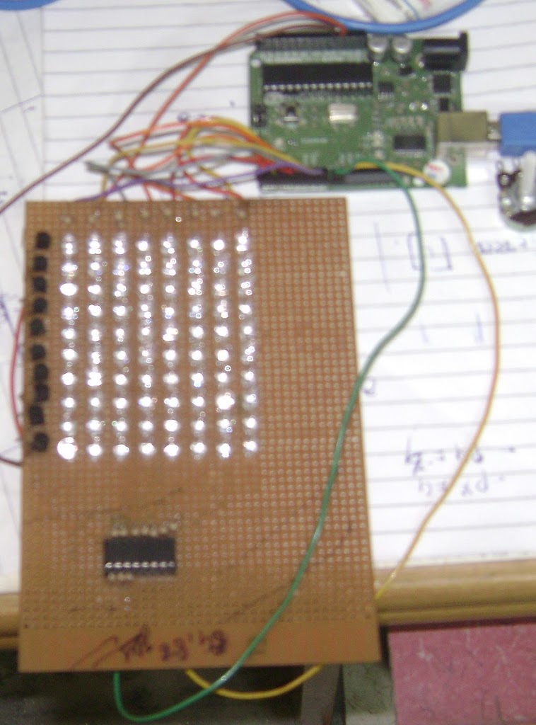
Step 2 : Soldering the Matrix
Soldering the LED matrix is a very tricky thing ,there are a lot of ways to do it and I will give you mine.
You need to connect all the positive leads of the LEDs in columns and the negative lead in rows.
Now you do this by taking the positive lead of the first LED and bend it down to the other LEDs, solder the pins which touch each other, from here take the last lead that
you soldered and bend it again down and repeat till you have all the positive leads connected in the column. snip the leads that you didn’t use.
Now the tricky part is connecting the negative pins in a row because you can’t bend them and solder like you did with the positive leads.My method saves lots of time and is a lot simpler.The trick is to put some tape or simple adhesive tape on the columns connections to isolate them from the negative pins and if you do that you can bend the negative leads too and connect them like you did with the positive ones.
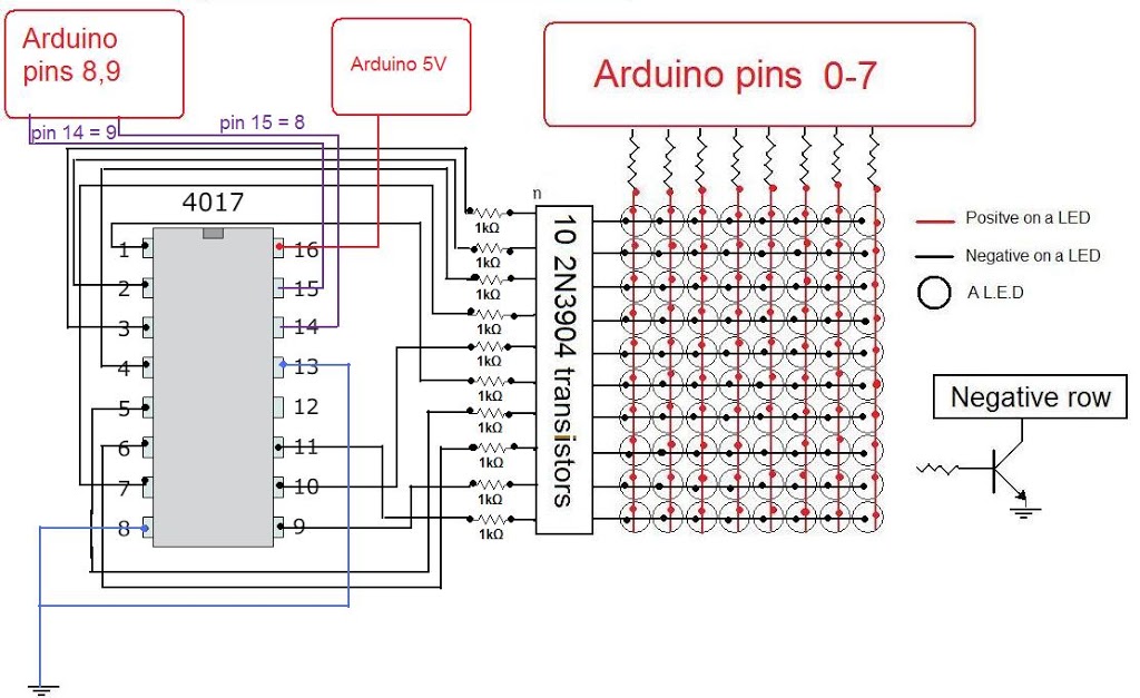
Circuit :
Connections
Via a resistor you connect each column to the arduino(pins 0-7).
The reset pin of the 4017 goes to pin 8 on the arduino and the clock pin goes to pin 9 on the arduino.
Step 3 : Multiplexing ?
So what is multiplexing:
It is basically a way to split information in to little peaces and send it one by one.
this way you can save a lot of pins on the Arduino and keep your program quite simple.
In our case we split the image that we want to display to 10 peaces (10 rows), We want to scan the rows of the matrix( light up one row at a time) and send info from the
Arduino to the columns.
All the columns are positives of the LEDs and the rows are negatives so if the first row is connected to ground and we send information to the columns we will only light
the first row.
To get a good display we need to scan the rows very fast, so fast the the human eye thinks that all of the rows are connected at the same time.
why the 4017:
For this LED matrix I wanted to use this useful IC.
The 4017 decade counter is used to allow multiplexing.
This IC basically scans the rows of the matrix( lights up one row at a time).
In our case we want to connect the rows to ground but the 4017 doesn’t build to sink current, so to solve this little problem we need to use a transistor with a resistor.
The 4017 has 10 output pins so we need 10 resistors and 10 transistors, we connect the 1K resistors to the outputs of the 4017 and the base of the transistor to the other
end of the resistor.
Then we connect the collectors of the transistor to the rows and the emitter to the ground.
(You can also use BC547 npn transistor)
Step 4 : Programming ->
have written a little program to make scrolling text and added all the letters and number( lots of work ), I used ports for my program because it saves space and easier to
handle.
If you don’t know how to work with ports on the arduino I recommend to go on the arduio web site a learn before you start.
If you want to make your own images I have made a little excel tool that will make writing images a lot easier.which you can find in the zip folder which I attached at the end.
And the last things is to not forget to unplug pins 0 and 1 when you upload your program because this pins also used as communication pins and may cause some errors with the program.
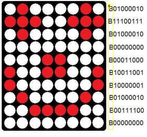 |
| The ‘B’ is for Arduino Language,so don’t worry about it. |
Download Project files from here
Its done.
I will happy if you make this and don’t forget to post your video here.
You can check my video.


BADelectRonics
January 22, 2012 at 11:19 pmGood job bro !
One question please , i wanna build it but with 40×7 led matrix using the CD4017 connected to ULN2803 in order to buffer the current . The matrix will be controlled by the microcontroller 16F628 . Can you tell me please if it will work or not ? because i liked your matrix led just wanna extand it .
Thanks for posting bro
sohil4932
January 29, 2012 at 10:16 amMeans Will you using 4 CD4017 or only 1?
Unknown
August 21, 2012 at 9:26 pmhi i wanted to build a 8×8 matrix using 74hc595 using this design sholud i simply replace 4017 with another 74hc595
sohil4932
August 25, 2012 at 6:30 amPranshu Kumar: Yes you can use this shift register IC instead of 4017. If you will use shift register than you have to do some changes in code.
Yunus Manullang
December 19, 2012 at 9:15 amhi sohil patel, i'm yunus from indonesia…
can we make this project use microcontroller Atmega8535?
sohil4932
December 20, 2012 at 12:41 pmYunus: ofcourse Yes why not.
But you need to change your coding standard as per your requirement.
Logic of code & circuit will remain same.
Unknown
December 31, 2012 at 7:31 amHi, i was searching for such type of thing, finally got it.Thanks for such informational blog.
LED Power Supply Driver with Dimmer
Unknown
January 27, 2013 at 3:30 pmHi, Is it possible to send pwm signals on this matrix?
sohil4932
January 27, 2013 at 3:37 pmWhat do you mean by pwm signals. And why want to send. Can I know the reason of doing that.
sohil4932
January 27, 2013 at 3:37 pmWhat do you mean by pwm signals. And why want to send. Can I know the reason of doing that.
Unknown
January 27, 2013 at 4:58 pmPWM signals can let you create an fading effect with the LEDs. An arduino mega has around 12 PWM capable pins, so i was wondering if we can fade the leds in and out instead of just of and on