Arduino + PS/2 Mouse
The PS/2 mouse interface originally appeared in IBM’s “Personal System/2” computers in the late 80’s and it remains a widely-supported interface. However, USB has quickly caught on these last few years and will eventually replace the PS/2 interface entirely.
|
Bit 7
|
Bit 6
|
Bit 5
|
Bit 4
|
Bit 3
|
Bit 2
|
Bit 1
|
Bit 0
|
|
|
Byte 1
|
Y overflow
|
X overflow
|
Y sign bit
|
X sign bit
|
Always 1
|
Middle Btn
|
Right Btn
|
Left Btn
|
|
Byte 2
|
X movement
|
|||||||
|
Byte 3
|
Y movement
|
|||||||
 (Plug) |
 (Socket) |
5-pin DIN (AT/XT): 1 – Clock 2 – Data 3 – Not Implemented 4 – Ground 5 – Vcc (+5V) |
 (Plug) |
 (Socket) |
6-pin Mini-DIN (PS/2): 1 – Data 2 – Not Connected 3 – Ground 4 – Vcc (+5V) 5 – Clock 6 – Not Connected |
 |
| Image is taken from Arduino Playground |
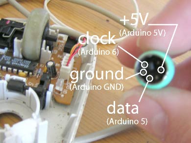
Plug the power pin into the +5 header pin, the ground to ground. Then connect the data and clock pins to two of the arduino digital pins. I uses Digital pin 5 as DATA and 6 as CLOCK.
Note : No of libraries are available for PS2 Protocol.Here I post one more link of the library called PS2 here.
#define MOUSE_DATA 5
#define MOUSE_CLOCK 6
PS2Mouse mouse(MOUSE_CLOCK, MOUSE_DATA, STREAM);
int motor1Pin1 = 9;
int motor1Pin2 = 10;
int motor2Pin1 = 8;
int motor2Pin2 = 7;
int motorsPinEnable = 2;
char mx = 0;
char my = 0;
void setup()
{
Serial.begin(38400);
mouse.initialize();
pinMode(motor1Pin1, OUTPUT);
pinMode(motor1Pin2, OUTPUT);
pinMode(motor2Pin1, OUTPUT);
pinMode(motor2Pin2, OUTPUT);
pinMode(motorsPinEnable, OUTPUT);
digitalWrite(motorsPinEnable,HIGH);
}
void loop()
{
int data[2];
mouse.report(data);
mx = data[1];
my = data[2];
if(my < 0)
backward(my);
else if(my > 0)
forward(my);
if(mx < 0)
right(mx);
else if (mx > 0)
left(mx);
}
void forward(int del){
Serial.println(“Begin”);
digitalWrite(motorsPinEnable,HIGH);
digitalWrite(motor1Pin1, LOW);
digitalWrite(motor1Pin2, HIGH);
digitalWrite(motor2Pin1, HIGH);
digitalWrite(motor2Pin2, LOW);
delay(abs(del)*2);
digitalWrite(motorsPinEnable,LOW);
Serial.println(“Einde”);
}
void backward(int del){
digitalWrite(motorsPinEnable,HIGH);
digitalWrite(motor1Pin1, HIGH);
digitalWrite(motor1Pin2, LOW);
digitalWrite(motor2Pin1, LOW);
digitalWrite(motor2Pin2, HIGH);
delay(abs(del)*2);
digitalWrite(motorsPinEnable,LOW);
}
void left(int del){
digitalWrite(motorsPinEnable,HIGH);
digitalWrite(motor1Pin1, LOW);
digitalWrite(motor1Pin2, HIGH);
digitalWrite(motor2Pin1, LOW);
digitalWrite(motor2Pin2, HIGH);
delay(abs(del)*2);
digitalWrite(motorsPinEnable,LOW);
}
void right(int del){
digitalWrite(motorsPinEnable,HIGH);
digitalWrite(motor1Pin1, HIGH);
digitalWrite(motor1Pin2, LOW);
digitalWrite(motor2Pin1, HIGH);
digitalWrite(motor2Pin2, LOW);
delay(abs(del)*2);
digitalWrite(motorsPinEnable,LOW);
}